Basic Boba Fett Display
This is a step by step guide to assembling the Basic Boba Fett Display DIY kit. If you need assistance, email dustin.westaby@gmail.com.
Overview
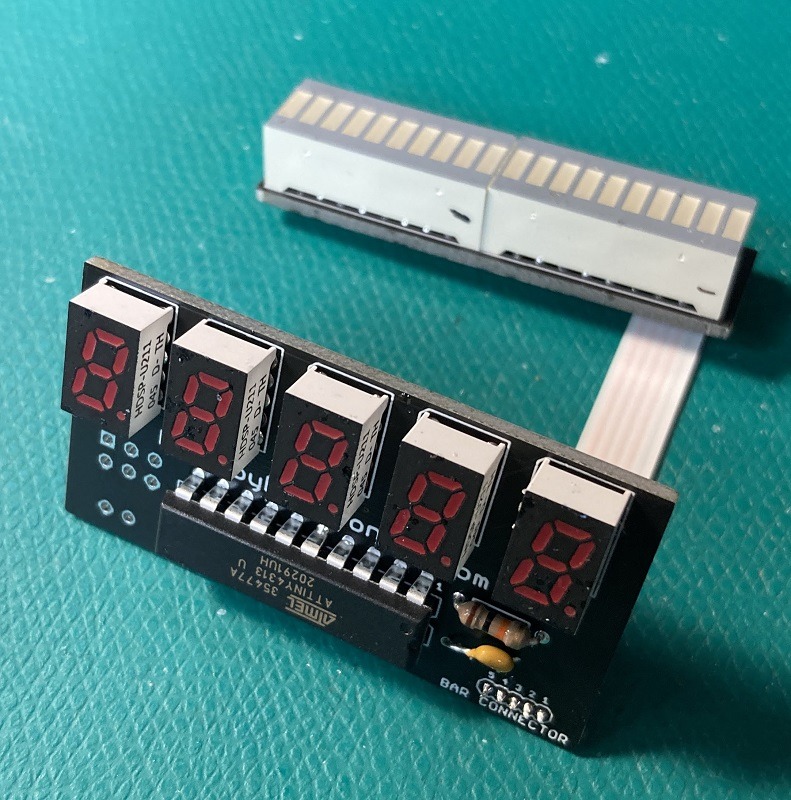
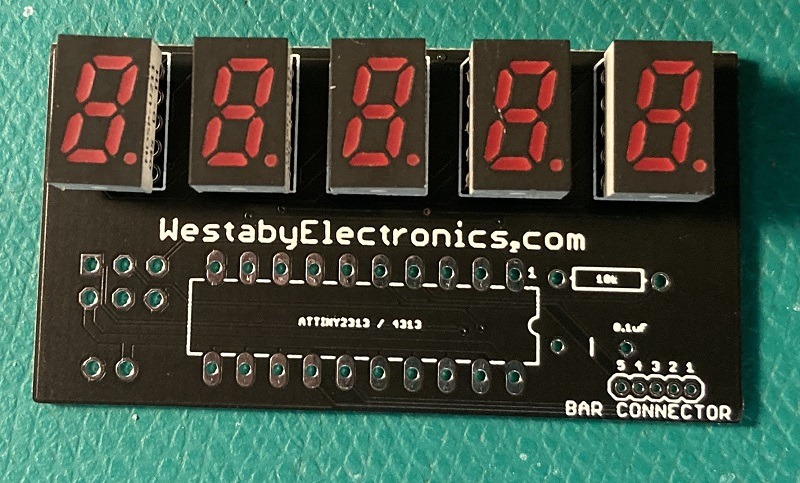
Your kit contains two PCBs, a 20 pin chip, and a ribbon cable. To complete the build, you will also need the displays, resistor, capacitor, and battery clip.
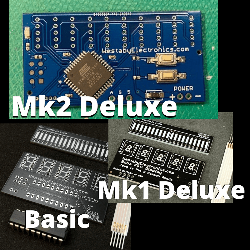
Versions
There are multiple versions of this kit. You are in the right spot if your PCB is black and you have a 20 pin chip to install.
Video tutorial
This kit has a video tutorial.
The latest version of the Basic Boba Fett Chest Display kit has a few differences from the video:
- No transistors
- Only one resistor
- Slim ribbon cable
- Single long 20 bar graph
Parts and tools
Part list
Your kit contains two PCBs, a chip, and a ribbon cable. To complete your kit, you will also need the items below.
- 1x AAx3 switched battery pack (12BH331/CS-GR)
- 1x LED bargraph red (DC20/20EWA)
- 5x LED 7 segment display red 0.3 inch CA (HDSP-U211)
- 1x spare resistor, 1k ohm
- 1x 1uF 10V ceramic capacitor (K105Z20Y5VE5TH5)
- 1x resistor 10k ohm 1/4W (CF1/4C103J)
One-click order the above parts from Mouser.
If something is out of stock: see the approved substitutes.
Recommended tools
- Soldering iron and rosin core electrical solder (flux inside)
- Flush cutters
- Wire stripper and small cutters
- Hot glue gun (optional, for strain relief)
Tip: If this is your first time soldering, a small starter kit can save time. Also, the Pace "Solder & Flux" lesson is a solid explanation of why flux solder matters: Basic Soldering Lesson 1.
Pre-assembly
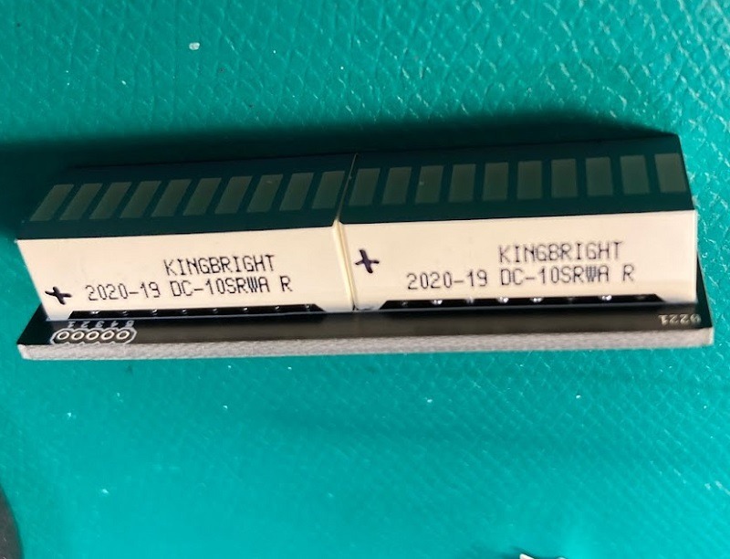
Before you assemble, take a moment to familiarize yourself with the parts.
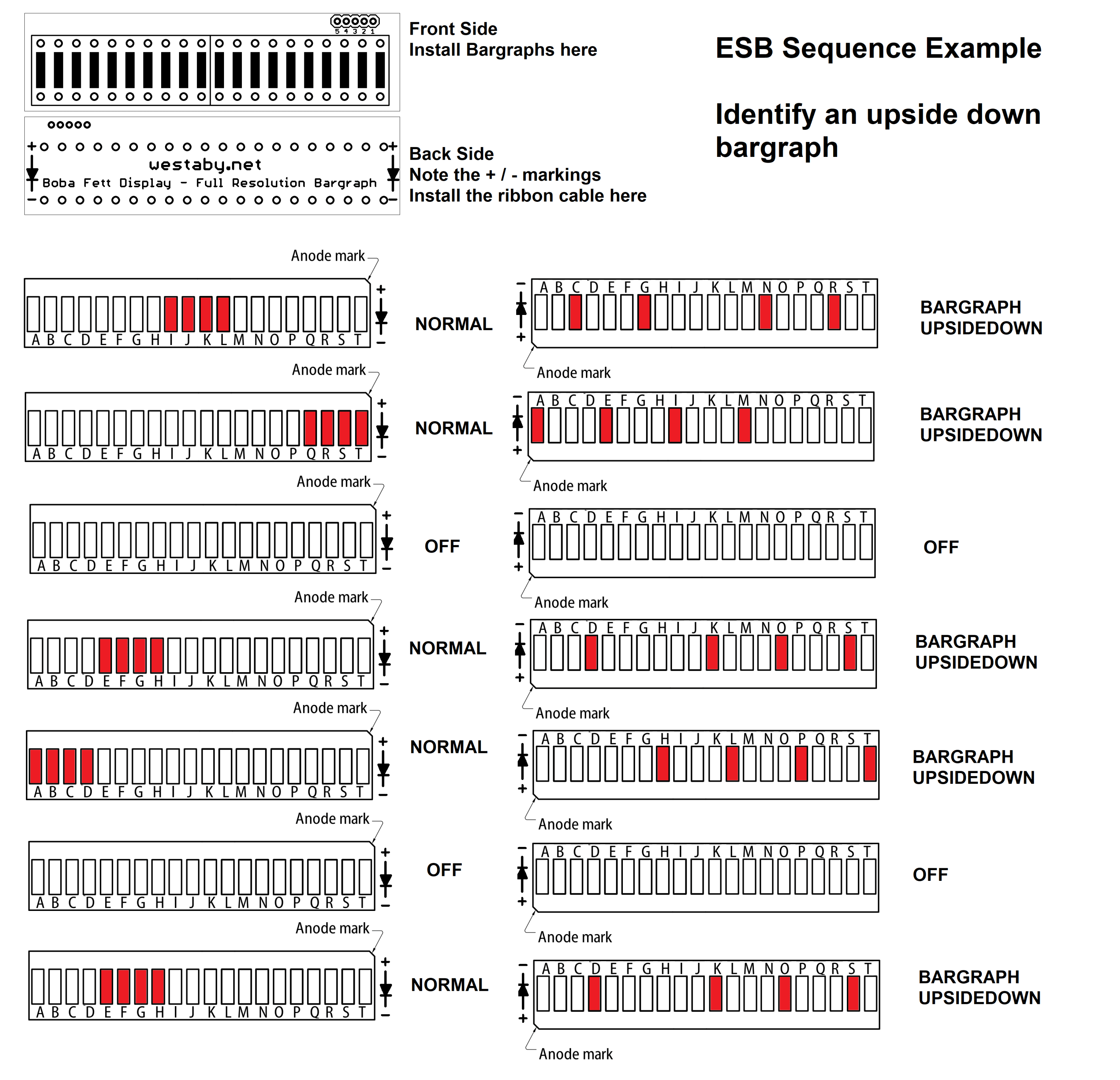
Do not skip this step. The displays can be inserted upside down, but will only work when installed the right way around.
Insert batteries into your battery clip, flip the power switch on, and hold the wires with the spare 1k ohm resistor (brown, black, red). Touch the bargraph display pins to find which side lights up.
When the bargraph lights up, you have the wires in the correct position. Use a marker to write + (positive) on the side with the red wire and resistor, and write - (negative) on the side with the black wire.
Repeat for the second bargraph display.
Assembly
Use electrical solder with flux inside. The flux removes oxidation from the metal, helps the solder flow, and transfers heat better. Your joints will be stronger and easier to make.
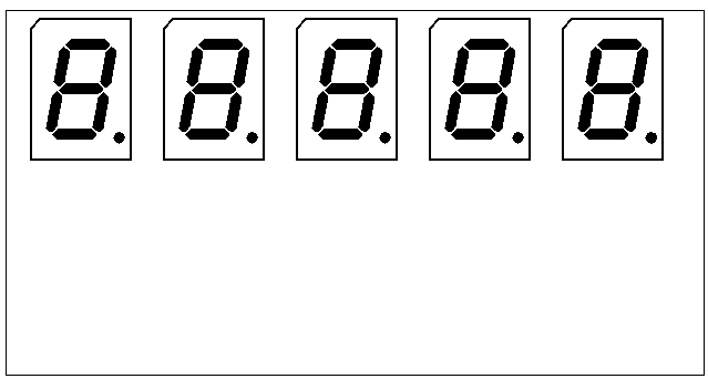
Character displays
Orientation matters. Your character displays have a small period dot on the front. Line it up with the reference photo. The displays will not work upside down.
You can install the displays and solder one at a time, or install all at once. After soldering, use flush cutters to remove extra pin length.
Chip, resistors, capacitor
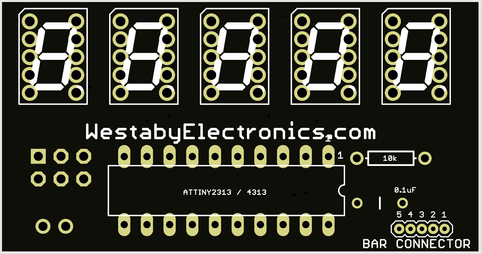
Orientation matters. Examine your 20 pin chip and you will see a notch on one end. This notch aligns with the drawing on the circuit board. Install the chip so the notch matches the drawing.
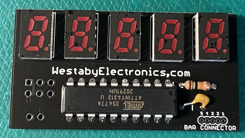
Install the resistor and capacitor. Solder in place and trim the excess leads with a flush cutter.
The part list included two resistors. Either will work here, but you will have better battery life if you use the brown, black, orange resistor (10k ohm).
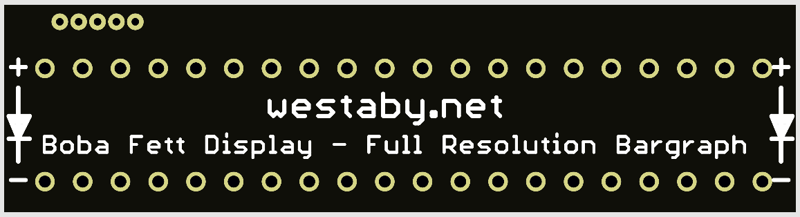
Bargraphs
You marked your bargraphs with +/- during pre-assembly. Now check the bargraph PCB. On either end you will see + / -. This must match your display markings.
Install the bargraph on the side with the bargraph drawing.
Ribbon cable
Caution: The ribbon cable can be brittle. Try to only bend it once.
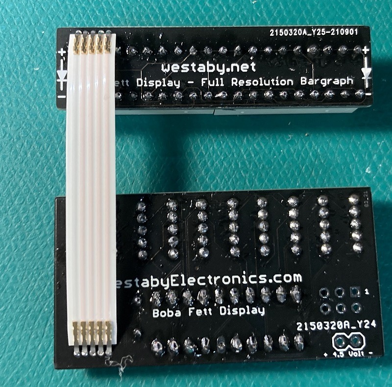
Orient the two display circuits as shown. Insert the ribbon cable, but do not bend yet. Solder the pins to the circuit.
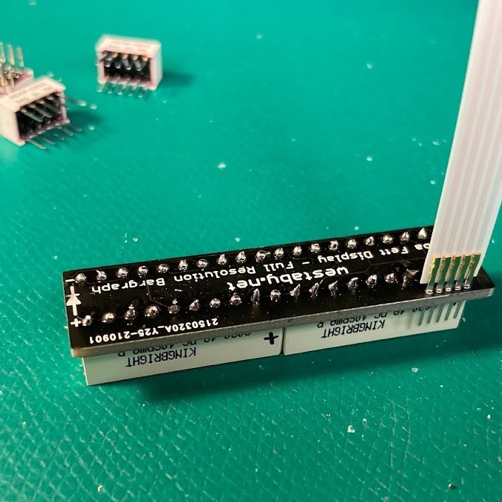
After soldering, use flush cutters to trim the extra pin length. Check for bridged connections (too much solder connecting adjacent pins). If you find a bridge, re-heat and quickly pull away to clear excess solder.
You can bend the ribbon cable now, or wait until after power-up testing. Hot glue on each end of the ribbon cable is recommended (see below).
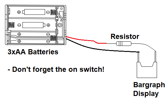
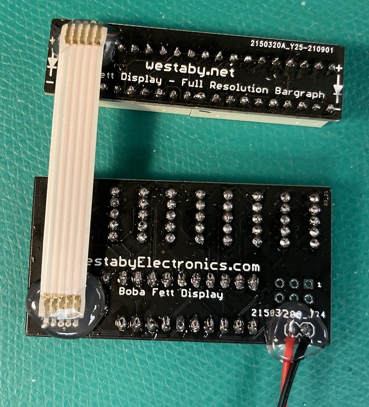
Power
The part list includes an easy-to-use switched 3xAA battery box. The battery box has two wires:
- Red is + (positive)
- Black is - (negative)
Wire the battery wires to the + / - connectors at the bottom of the circuit.
Hot glue
Once everything looks good and your circuit powers up correctly, you can add strain relief to the wires and ribbon cable.
Add hot glue to either end of the ribbon cable, above and below. This allows the cable to flex, but not stress the solder joint.
Mounting in your costume
The two circuits are separate to fit a variety of costume designs. You can expand or narrow the distance as needed.
For very short lengths, you can fold the ribbon cable in a zig-zag pattern to make it extra short.
Use hot glue or epoxy to affix to your armor. The battery pack can be heavy, so make a pocket shelf or use heavy-duty velcro.
To help with alignment and block light leaks, you can use craft foam. Cut to match the circuit size, then glue the foam and circuit into your armor.
Troubleshooting
Parts out of stock or backordered
This happens from time to time. You will need a replacement part. Add all the Mouser project parts to your cart, delete the backordered part, then add one of the substitutes below.
Be careful when picking your own substitutes. The parts below are pre-approved.
There are two reds to pick from: Bright Red (brighter) and High Efficiency Red (dimmer). High Efficiency Red photographs better, but Bright Red is better for outdoor cosplay. Pick the same red for both the bargraph and character display.
| Part | Quantity | Mouser substitutes | Definitions |
|---|---|---|---|
| Character display | 5 |
HDSP-U101 HDSP-U111 HDSP-U201 HDSP-U211 |
U1xx = Bright Red U2xx = High Efficiency Red Ux0x = Gray background Ux1x = Black background |
| Bargraph display | 1 or 2 |
DC10SRWA DC10EWA DC20/20SRWA DC20/20EWA |
DC10 = 10 bars DC20 = 20 bars SRWA = Bright Red EWA = High Efficiency Red |
| Resistor 1k | 1 | TBD | |
| Resistor 10k | 1 |
CF1/4C103J CFS1-4CT26A103J CF1-4CT52R103J CFS1-4CT52R103G CFS1-4CVTR103J |
1/4 = 1/4 watt 103 = 10k ohms |
| Capacitor | 1 | TBD | |
| Switched AA battery clip | 1 |
12BH331/CS-GR 12PH331/IP-GR 12BH431/CS-GR PW-3AA |
IP = water resistant 331 = AA 431 = AAA |
Dark segment on a character display, or segments not lighting correctly
Check your solder work for places with too little solder or too much solder. Re-melt each joint and touch up as needed. Adjacent joints should not be touching.
Solder touch-up video: https://www.youtube.com/watch?v=OaBRak0HnQs
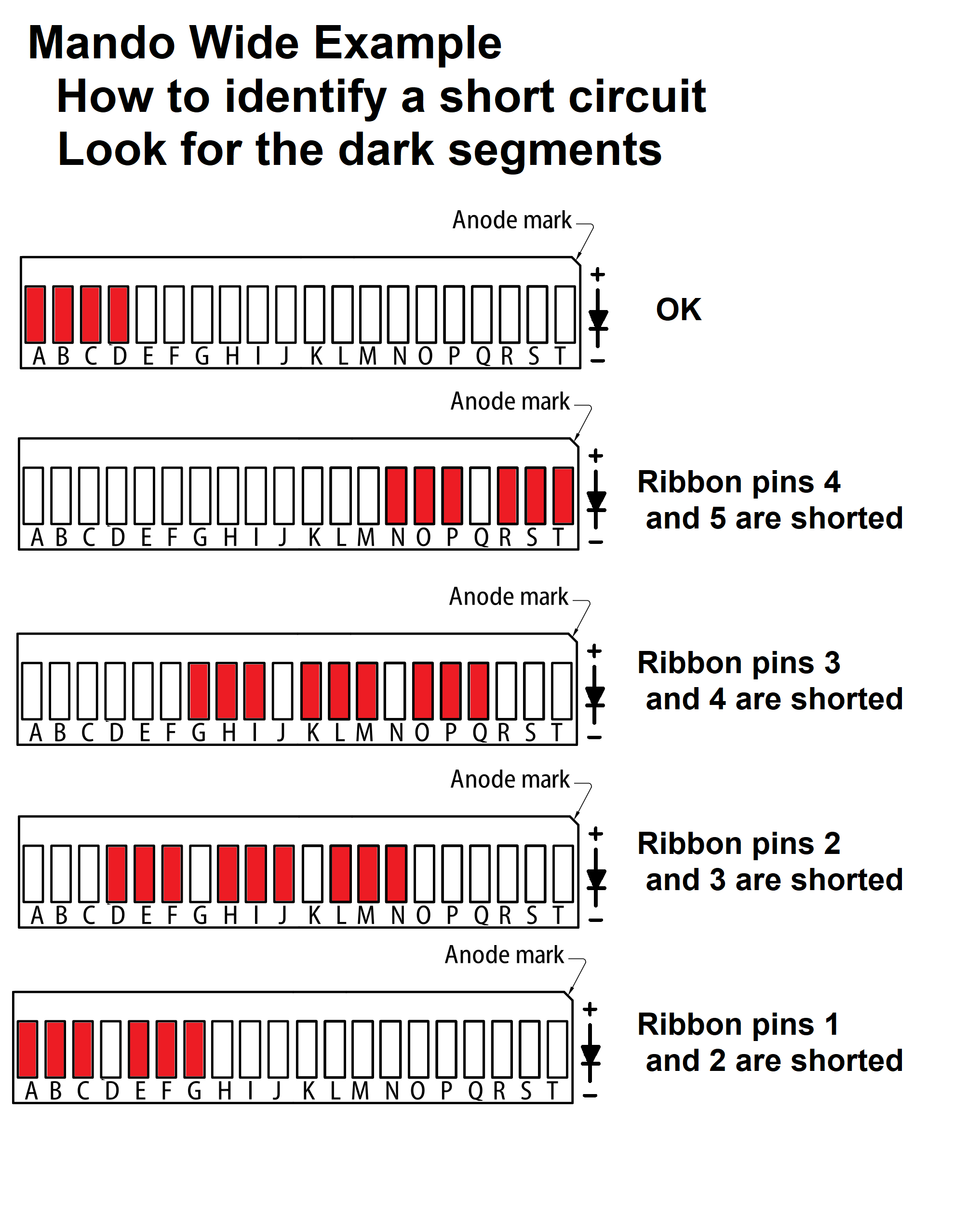
Bargraph looks scrambled
Common cause 1: Your bargraphs are installed backwards. Remove and flip them around.
Common cause 2: The bargraph ribbon cable is shorted from too much solder. Use a smartphone magnifier to inspect both ends of the ribbon cable for solder bridges. Re-heat and pull away solder until the excess is gone, wiping the iron each time.
No lights at all
You may also notice the chip or batteries overheating. Switch off right away. The chip can burn out and you are draining your batteries.
- Check your power wires. Typically, red is + and black is -.
- Check the switch on your battery pack. Make sure it is on.
- Use a fresh set of batteries. The display will be very dim with less than about 3V.
- Touch up your solder joints and look for bridges between adjacent pins.
Solder touch-up video: https://www.youtube.com/watch?v=OaBRak0HnQs
Broken ribbon cable
The ribbon is flexible, but the joints are not.
- Option 1: Carefully add solder to each broken joint to reattach the cable.
- Option 2: Use your own wire instead of the ribbon.
- Option 3: Purchase a replacement ribbon. Email: dustin.westaby@gmail.com
Once fixed, add hot glue to prevent the joints themselves from flexing.