This is a step by step guide to assembling the Mk2 Deluxe Boba Fett Display DIY kit.
If you need assistance, email dustin.westaby@gmail.com
Versions
There are multiple versions of this kit. You are in the right spot if the your pcb is blue in color.
The Mk2 Deluxe Boba Fett Display circuit now includes buttons on the back to cycle forward / back through the built in animations.

Part List
Your kit contains two PCBs and a ribbon cable. To complete your kit, you will also need the displays and battery clip.
- 1x AAx3 Switched Battery Pack (12BH331/CS-GR)
- 1x LED Bargraph Red (DC20/20EWA)
- 5x LED 7 Segment Display Red 0.3″ CA (HDSP-U211)
- 1x Spare Resistor, 1k ohm
Click here to one click order the above parts from Mouser.
Click here for some alternate part numbers if anything is out of stock.
USB Cable (optional)
If you want to just run on AA batteries you can skip this step.
To power your display using a Portable USB Power Bank, the recommended USB cable is the 4448 from adafruit. It is an easy to use jumper wire breakout of a USB A plug.
- Jumper Pin USB Cable https://www.mouser.com/ProductDetail/485-4448
- Right Angle Header https://www.mouser.com/ProductDetail/3-644457-2
Wiring:
- Red wire connects to 5V
- White (do not use)
- Green (do not use)
- Black wire connects to GND
You can splice in your own USB cable, but the color code may be different. Use a multimeter to double check.
Pre-Assembly
Before we assemble, take a moment to familiarize yourself with the parts.
DO NOT SKIP THIS STEP. The displays can be inserted into the pcb upside down, but will only work when installed the right way round.

The above drawing demonstrates how to test the bargraph polarity. The bargraph will light up one way but not the other.
Insert batteries into your battery clip, flip the power switch on, and hold the wires with the spare 1k ohm resistor. Touch the bargraph display pins to find which side lights up.
When the bargraph lights up, you have the wires in the correct position. Use a marker to write + (positive) on the side with the red wire / resistor, and write – (negative) on the side with the black wire.
If your kit has a second bargraph, repeat for the second bargraph display.
Assembly
It is important that you use electrical solder. You need solder with flux inside. The flux removes oxidation from the metal, helps the solder flow, and transfers more heat from the solder iron. Your joints will be stronger and faster.
TIP: If this is your first time soldering, save some time and buy a $20 kit (link) that comes with the solder iron, solder, wire stripper, and cutter. In addition, this educational video is quite old, but is the BEST explanation of how to solder and why we use flux solder for electronics. Basic Soldering Lesson 1 – “Solder & Flux”
Character Displays
Orientation matters. Your character displays have a small period dot on the front. Line it up with the photo below. The displays will not work upside down.

You can install the displays and solder one at a time, or all at once.
Once you solder the pins, use a flush cutter to remove the extra pin length.
Bargraphs
You did the pre-assembly step and marked your bargraphs with +/- already right? Now is the time to look at the bargraph PCB. On either end you will see + / – written. This MUST match up with your display’s +/- markings.
Install the bargraph on the side with the bargraph drawing.


Ribbon Cable
Caution: The ribbon cable can be brittle, be careful to only bend once.
Orient the two display circuits as shown. Insert the ribbon cable, but do not bend yet. Solder the pins to the circuit.

[NEED PHOTO OF BOTH CIRCUITS]
After soldering, use a flush cutters to trim the extra pin length.
Check for any bridged connections, where there is too much solder and two pins are connected. Use your solder iron to re-heat and quickly pull away to clear out any extra solder.
Repeat for the other side.
You can bend the ribbon cables now, or wait until after power up testing. Recommend hot glue on each end of the ribbon cable (see below).
[NEED PHOTO]
Power
You can power from a variety of power sources. The part list includes an easy to use switched 3xAA battery box. You can also power using a spliced/jumpered usb cable and a portable USB battery bank (see above).
Voltage range needed is 4V to 6V.
The 3xAA battery box has two wires, red and black.
- Red is + (positive)
- Black is – (negative)
Wire the battery wires to the + / – connectors at the bottom of the circuit.
Hot Glue
Once everything looks good and your circuit powers up ok, you can take extra steps to add strain relief to the wires and ribbon cable.
Add hot glue to either end of the ribbon cable. Above and below. This allows the cable to flex and bend, but not bend or stress the solder joint.
Animation Selection
There are 15 animations in total to pick from. The ESB, ROTJ, and Mando animation sequences were designed using the amazing in-depth research from the folks on The Dented Helmet forum.
- ESB
- ROTJ
- Mandalorian Wide Bargraph
- Mandalorian Narrow Bargraph
- Larson Scanner
- Side to Side
- Side to Side Inverted
- Spiral
- Spiral Inverted
- Updown
- Snake
- Inverted ROTJ
- Inverted Mandalorian Wide Bargraph
- Inverted Mandalorian Narrow Bargraph
- Inverted Larson Scanner
To choose the animation, use the two buttons on the back of the circuit.
- Press one button to move to the next animation.
- Press the other button to move to the previous animation.
Animation selections are saved and will persist between power cycles.
Mounting in your Costume
The two circuits are separate to fit a variety of costume designs. You can expand or narrow the distance as needed.
For very short lengths, you can also fold the ribbon cable in a zig zag to make it extra short.
Use hot glue or epoxy to affix to your armor. The battery pack can be heavy, make a pocket shelf or use heavy duty velcro.
To help with alignment and block light leaks, you can use craft foam. Cut to match the circuit size, then glue the foam and circuit into your armor.
Troubleshooting
Parts out of stock? Backordered?
This happens from time to time. You will need a replacement part. Go ahead and add all the mouser.com project parts to your cart and delete the backordered one. Then add one of the subs below.
Be careful in picking your own substitute parts. The parts list below are pre-approved as ok.
There are two colors of red to pick from. Bright Red (brighter) and High Efficiency Red (dimmer). In my opinion the high efficiency red photographs better, but the bright red would be better suited for outdoor cosplay. Make sure to pick the same color red for both the bargraph and character display.
| Part | Quantity | Mouser Substitutes | Definitions |
| Character Display | 5 | HDSP-U101 HDSP-U111 HDSP-U201 HDSP-U211 | U1xx = Bright Red U2xx = High Efficiency Red Ux0x = Gray Background Ux1x = Black Background |
| Bargraph Display | 1 or 2 | DC10SRWA DC10EWA DC20/20SRWA DC20/20EWA | DC10 = 10 Bars DC20 = 20 Bars SRWA = Bright Red EWA = High Efficiency Red |
| Resistor 1k | 1 | TBD | |
| Switched AA Battery Clip | 1 | 12BH331/CS-GR 12PH331-IP-GR 12BH431/CS-GR PW-3AA | IP = Water Resistant 331 = AA 431 = AAA |
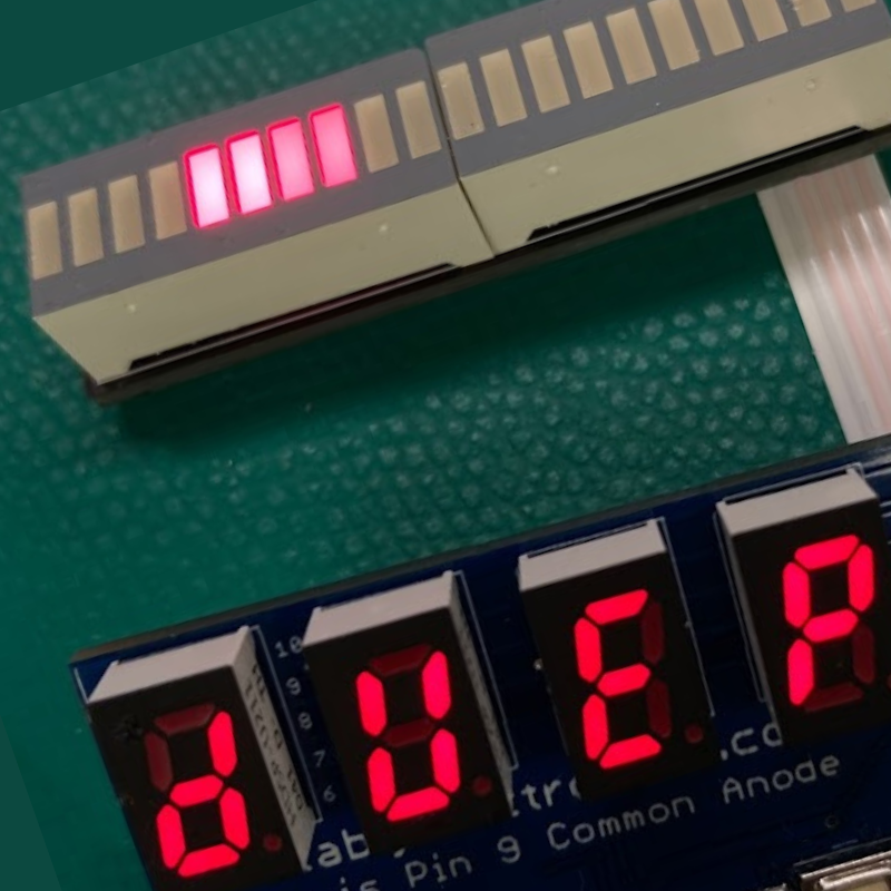
Dark character display?
Early versions of the Mk2 need an extra wire installed on the leftmost character display. Your kit arrived with an extra wire, strip the ends with your finger nail and solder as shown in the photo.

The wire connects the A pin to pin 9 on the first character display.

Dark segment on one of the character displays?
Display not light up right?
Check your solder work for places with not enough solder or too much solder.
Bargraph display look scrambled?
Your bargraphs are installed backwards. Use a hot air rework station to remove the displays and flip around. Here is a comparison of the ESB animation sequence on a backwards installed bargraph.

Your bargraph ribbon cable is shorted (too much solder). Use your smartphone’s magnifier app to look for any solder between pins on either end of the ribbon cable. If you find any, re-heat and pull the solder away with your iron, wiping off the iron each time, until the excess solder is gone.

No lights at all?
Check your power wires. Typically, the red wire is + (positive) and the black wire is – (negative).
Check the switch on your battery pack. Make sure it is ON.
Use a fresh set of batteries. The display will be very dim with less than ~3V.
Broken ribbon cable?
Doh! The ribbon is flexible, the joints are not.
- Option 1: You can carefully add solder to each of the broken joints. Mending the cable back on.
- Option 2: Use your own wire instead of the ribbon.
- Option 3: You can purchase a replacement ribbon. Email: dustin.westaby@gmail.com
Once fixed, add hot glue to prevent the joints themselves from flexing.


